

1.2.1: Conceptual model#
The conceptual model is a description, in plain language, of what is in the system and how it works. It decides which parts of the real system matter for the question and which can be left out.
Its central judgement is selection: where should the modeller draw the line between what the model represents and what it ignores? Nikolic, van Dam and Lukszo organise that work into three connected activities [1]. Explore them in the tabs below.
A model is built to address a problem, usually a gap in understanding about why a system behaves the way it does. The modeller pins down the macro-level pattern that needs explaining and turns it into a specific, answerable research question, such as “under what conditions does this pattern appear?”, rather than something vague (“how does traffic work?”) or so broad that no single model could settle it. Without a clear question, every later choice becomes arbitrary [1].
The modeller decides what is inside the system and what is outside it, names the entities it contains and the states they carry, describes the environment they sit in, and picks out the interactions that drive the pattern of interest. A key choice here is the grain size, the level of detail: the same city could be represented by individual people, by households, or by whole neighbourhoods, and the right grain is the coarsest one that still captures the mechanism behind the question [1]. Grain size is one of the two pivotal choices at this stage; the other, drawing the system boundary, is taken up in Section 1.2.1.2.
Terms that seem clear in conversation often turn out to be ambiguous once they are written down. Because a computer cannot work with ambiguity, the modeller fixes the meaning of every concept the model uses before any code is written [1].
Each of these choices is a deliberate simplification, and the modeller should be able to say why each exclusion is acceptable for the question at hand. The output of the stage is normally a short written description supported by a simple overview diagram of the entities, their environment, and their interactions, so that a reader can grasp the model’s structure at a glance [1].
1.2.1.1: The traffic example#
The traffic question becomes manageable only after the real road has been reduced to the parts that could generate congestion without an external obstruction. Vehicles remain as individual entities because their differences in position and speed matter; the road becomes a loop so that traffic can circulate without entrances or exits; and each driver is represented only through a response to the gap ahead. Weather, junctions, overtaking, and route choice are excluded because they are not needed to test whether car-following alone can produce a jam [2]. The diagram records that boundary before any equation or code is written.
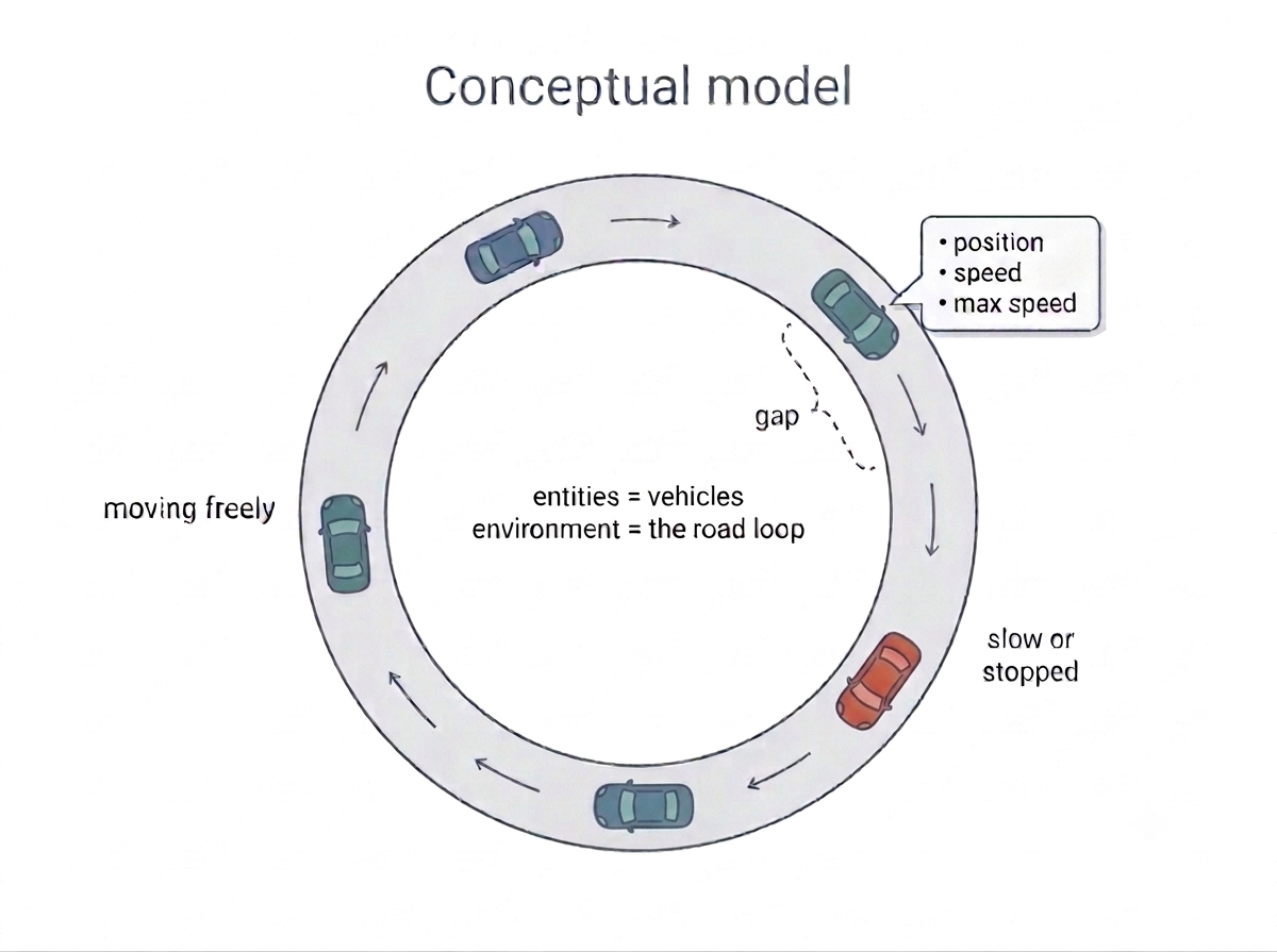
Fig. 5 Figure 1.5 Conceptual model of the traffic system: a single-lane loop of road (the environment) carrying vehicles, each with a position, a current speed, and a preferred maximum speed, reacting only to the gap to the vehicle ahead.#
The same three activities now become concrete in one worked case. Work through the tabs from left to right: each records a modelling decision and the choice made for the single-lane traffic model.
Formulate the problem
Observed pattern Traffic jams sometimes appear without an accident or bottleneck.
Research question Can vehicle interactions alone create spontaneous congestion, and at which traffic densities [2]?
Why this works The question is specific enough for one model to answer.
Identify the system
Entities: individual vehicles
Environment: a single-lane loop
States: position, current speed, preferred maximum speed
Interaction: respond to the gap ahead
Weather, vehicle type, driver identity, overtaking, and wider road geometry stay outside the model because the question concerns car-following alone [2].
Formalise the concepts
Position: location on the loop
Speed: change in position per simulated time unit
Gap: distance to the next vehicle ahead
Following: adjust speed in response to that gap
These definitions replace everyday ambiguity with concepts the formal model can specify precisely [1].
Together, the three decisions form the conceptual model: a focused question, a deliberately bounded system, and concepts precise enough for the next stage to formalise.
1.2.1.2: Drawing the system boundary#
The traffic example exposes two choices that are easy to confuse. The system boundary decides what the model includes at all; the grain size decides how finely the included parts are represented. Both choices are judged against the research question.
Choice |
What it controls |
|---|---|
System boundary |
Question: Which entities, processes, and environmental features count as inside the model? |
Grain size |
Question: How finely are the parts inside represented: for example, individuals, households, or neighbourhoods? |
In the activity below, apply the first choice to the traffic question. Decide item by item what belongs inside and what stays outside, using the question rather than the detail’s realness as your guide.
Notice what did the sorting: not which details are real, but which the question depends on. That is what makes drawing the boundary a deliberate act of judgement rather than a matter of including everything you can think of.
Drawing the boundary is only one of the stage’s two pivotal choices; the other is the grain size, and the activity below asks you to tell the two apart.
Notice that neither choice turned on how real a detail is: the boundary decides what is kept inside, the grain size decides how finely it is resolved, and both trace back to the question.
With the entities, environment, interactions, and concepts named in plain language, the next stage, 1.2.2: Formal model, turns this description into a precise, unambiguous specification.
Key takeaways#
Key takeaways
The conceptual model decides, in plain language, what is in the system, what is left out, and how the parts behave.
It involves three activities: formulating the problem and question, identifying the entities, environment, and interactions (and the grain size), and pinning down the meaning of every concept.
Each boundary and grain choice is a deliberate simplification the modeller should be able to justify.